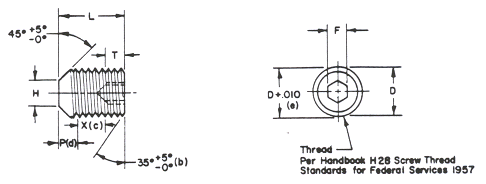
| THREAD | D |
F |
H |
SELF-LOCKING DESIGN DATA |
T |
||
P(d) |
|||||||
MAX |
MIN |
MAX |
MIN |
50o MAX |
MIN |
||
| #4-40NC-3A | .112 | .0510 | .0500 | .061 | .051 | .062 | .040 |
| #6-32NC-3A | .138 | .0635 | .0625 | .074 | .064 | .076 | .050 |
| #8-32NC-3A | .164 | .0791 | .0781 | .087 | .076 | .085 | .062 |
| #10-32NF-3A | .190 | .0947 | .0937 | .102 | .088 | .093 | .075 |
| 1/4-28UNF-3A | .250 | .1270 | .1250 | .132 | .118 | . 116 | .100 |
| 5/16-24UNF-3A | .3125 | .1582 | .1562 | .172 | .156 | .136 | .125 |
| 3/8-24UNF-3A | .375 | .1895 | .1875 | .212 | .194 | .151 | .150 |
| 1/2-20UNF-3A | .500 | .2520 | .2500 | .291 | .270 | .188 | .200 |
| L LENGTH TOLERANCE |
DASH NUMBERS (a) |
||||||||
| #4-40 | #6-32 | #8-32 | #10-32 | 1/4-28 | 5/16-24 | 3/8-24 | 1/2-20 | ||
1/8 |
+.010 |
1 | 2 | 3 | 4 | ||||
| 3/16 | 5 | 6 | 7 | 8 | 9 |
|
|||
| 1/4 | 10 | 11 | 12 | 13 | 14 | 15 | |||
| 5/16 | 16 | 17 | 18 | 19 | 20 | 21 | |||
| 3/8 | 22 | 23 | 24 | 25 | 26 | 27 | 91 | 92 | |
| 7/16 | 89 | 90 | 30 | 31 | 32 | ||||
| 1/2 | 33 | 34 | 35 | 36 | 37 | 38 | 39 | 40 | |
| 9/16 | 41 | 42 | 43 | 44 | 45 | ||||
| 5/8 | 46 | 47 | 48 | 49 | 50 | 51 | 52 | 53 | |
| 3/4 | +.015 | 54 | 55 | 56 | 57 | 58 | 59 | 60 | |
| 7/8 | 61 | 62 |
|
63 | 64 | 65 | 66 | ||
| 1 | 67 | 68 | 69 | 70 | 71 | 72 | |||
| 1-1/4 | 73 | 74 | 75 | 76 | |||||
| 1-1/2 | +.020 | 77 | 78 | 79 | 80 | ||||
| 1-3/4 | For lengths above heavy line see note (g) |
81 | 82 | 83 | |||||
| 2 | 84 | 85 | 86 | ||||||
| 2-1/2 | +.031 | 87 | |||||||
| 3 | 88 | ||||||||
This Standard takes precedence over documents referenced herein. |
|||||||||
P.A. NAVY - WP Other Cust |
TITLE SETSCREW, HEXAGON SOCKET, FLAT POINT, 250°F |
MILITARY STANDARD | |||||||
| MS18065 | |||||||||
PROCUREMENT SPECIFICATION |
SUPERSEDES: |
SHEET 1 OF 2 | |||||||
| APPROVED 4 JUNE 63 REVISED A 22 DECEMBER 64 | |||||||||
FED.SUP CLASS |
||
|
(a) Unassigned dash numbers shall not be used. (b) Socket end of screw shall be flat and chamfered. The chamfer shall extend to the minor diameter of the thread and the edge between flat and chamfer shall be slightly rounded. (c) Location of effective locking area "X" shall be in accordance with MS 15981 except as noted herein. (d) PMax. = Maximum point plus minimum of 1 thread pitch. For ease in starting, locking element shall not be effective within this area. (e) Maximum major thread diameter plus .010 = Maximum ring gage diameter that locking region of part must pass through freely or with finger pressure. (f) See MS51965 and MS51966 for set screws without self-locking feature. (g) As MIL-F-18240 doesn't establish torque requirements for items above heavy line, only a positive indication of torque is required. MATERIAL:
Steel, alloy (See Procurement Specification). Hardened by quenching In
oil from the hardening LOCKING DESIGN FINISH: Steel: Cadmium plate Specification QQ-P-416, Type II, Class 3. Except that paragraph 4. 4. 5 is not applicable. EXAMPLE
|
||
P.A. NAVY - WP Other Cust |
TITLE SETSCREW, HEXAGON SOCKET, FLAT POINT, 250°F |
MILITARY STANDARD |
| MS18065 | ||
| PROCUREMENT SPECIFICATION FF-S-200 & MIL-F-18240 |
SUPERSEDES: | SHEET 2 OF 2 |
| APPROVED 4 JUNE 63 REVISED A 22 DECEMBER 64 | ||
All prints are for reference purpose only. CAM-TECH manufactures to the latest revision.
